And so, presenting the DreamSteamTeam!
SteamBot - (Main character for the animation)
 GentBot
 BoilerBot
 ProfBot
 KidBot
Famous 5, eat your heart out
GentBotBoilerBotProfBotKidBotFamous 5, eat your heart out
 The first step was to give BoilerBot a more 'dirty' colour scheme. Opening photoshop, I took a dark, earthy green, and smeared black smudges all over it, creating a nice 'coal' effect. The trim was also made lighter and more prominent (Giving more of an impression of something like steel)
 Next up was to try and build the flat-cap most coal workers wore. I started off with a simple cube on top of the head, and spent a good 5 minutes playing around with the 'editable poly' tool. The 'Soft Selection' option helped greatly here too.
 The main cap was finished off with a blast of 'turbosmooth' and given a denim texture to it (Stolen from the failed texture I used on the overalls).
 The 'stripe' to the cap was made from a chopped-up sphere. A combination of the hemisphere and "Slice from / to" helped to cut the sphere down to a single, rounded wedge. It was finished off with a bit of 'edit poly' to pull some of the vertexes out to cover the cap properly.
 The final stage of the cap was simply to add the bill. This was made from a heavily-flattened sphere (Thanks to the humble 'scale tool'), and in 'editable poly' mode, the centre was raised up slightly, to create an overall bend. And with that, BoilerBot was finished! (For now anyway...)
 Aww, isn't it cute!
 So to begin with: I made the spectacles. The first step was to make a pair of cylinders and use the built-in "Slice from/to" options to chop them into semi-circles.
 The rims were built from a trio of tori (Plural of 'Torus'), all hit with the "Slice to / from" tool. A pair of half-tori built the frame, and a smaller segment of one created the bridge. At this point, I left the model for a while. Whilst I wanted to add a beard, I realised that the hair/fur modifier would eat up far too much processor to be of any real use. However, a brainwave hit me the next day:


The finishing touch was the all-important mortar-board. A pretty easy creation as you can probably tell... 1 sphere and a rectangle on top. Simple additions, but now we have a fully functional ProfBot!
 The first step was to create a nice colour scheme for the GentBot, and a nice royal green suited it nicely. It was also given a fancy golden / bronze trim, instead of the metallic silver of the original. This gave the new Bot a little bit more 'style' compared to its counterparts.
 The monocle was a nice and easy addition. A torus with a flat cylinder for the centre. The texture of the cylinder was given a high specular level with opacity at around 5%, giving the perfect impression of glass. The string leading from the monocle was a combination of the 'Helix' Line tool, with the 'Loft' Compound Primitive, using a circle as the base. (If you've forgotten how to do it: create a 'Helix' line, and place a circular one at the tip. Then, under the 'compound primitives', you will find 'loft'. Select the circle, to act as the shape, and then select "set Path". Click the helix and it will use the line as the path: Creating a tube). With the tube, all I had to do was shrink the circle and play with the scale tool until I was happy.
 The hat was an incredibly easy addition. I created a cylinder, and in the 'Edit Poly' Mode, lifted up all of the vertices on the outside of the hat to create the base: And the top was merely a large, upside-down cone.
 Another shorter cone created the band around the base of the top hat. It was nearly done... but something was missing...
 Bingo! What is a gent without the long, twiddly moustache? The loft tool once again saved the day. I started with a basic line tool, and curved it around into the little loop on the tips. Add the loft and it was pretty much done. I created a single half of the 'tache with this, and simply duplicated and flipped it around. And there we have it: A distinguished looking SteamBot!
 From this bit, all I needed to do was bring the bulk of the undercarriage up from below (using the same process outlined in Part C). The only difference this time was that it worked better if the undercarriage "overshot" and flew too high before going back down into its correct position. It looked better and allowed me to "throw" SteamBot into the air. Another key thing about animaiton is ENERGY. I could have just had the undercarriage lift and push SteamBot into position... but throwing him in the air packs a lot more of a visual impact.
 The final step of the animation (So far at least...) was the have the train tracks fly in. I'll give you 3 guesses how I went about doing that one!
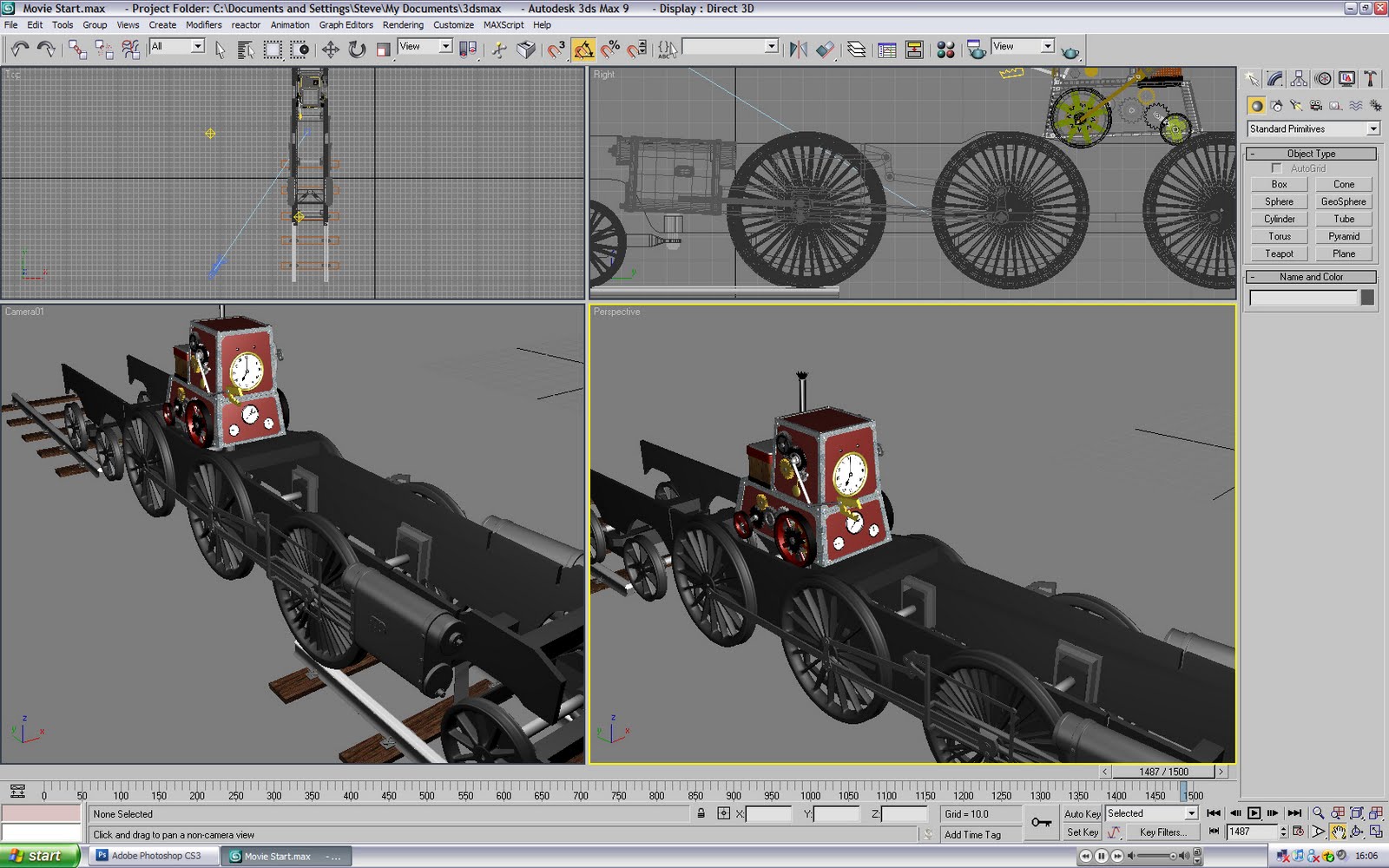 And there we have it! The details and tricks used to make the beginning of the animation. Hope some of the tips are useful!
 The first thing that the eagle-eyed readers of this blog would have spotted was the fact that the screenshots have translucent wheels in the scene next to SteamBot. On rendering, these wheels are actually completely invisible (Right Click -> Object Properties -> Visibility -> Set to 0). In fact, most of the undercarriage is invisible. I merged the entire undercarriage model with this one, and set its visibility down to 0.
 The animaiton of the flying pieces is basically a very clever process (If I do say so myself). The secret is that I simply worked backwards.
 You see, having the finished model meant that all the pieces were in the correct place. All that I needed was to have the pieces flying in from far away. So instead of starting with a piece a long way away, and then keyframing it into the scene... I started with the finished model, and keyframed the train part flying AWAY from the scene. Once I had done this, all I had to do was swap the 2 keyframes around (If you haven't tried this, all you have to do is click and drag the keyframes on the timeline to move them). So instead of the animation starting at the centre, and flying out of the scene... the animation now started out of the scene, and flies back to its original starting point in the correct position. Sneaky eh?
 The only step to do from this was to stagger all the keyframes and movements to allow the pieces to cascade onto the model. This was merely a simple case of dragging the keyframes around to where they fit best, so that they 'finished' up on the model at different times.
 This process was repeated with the entire model. All the wheels, cylinders, axles, extra carriages all flew in from this exact process. Use the original point as the guide, build the keyframes from it: Then swap them around. Repeat until looking awesome
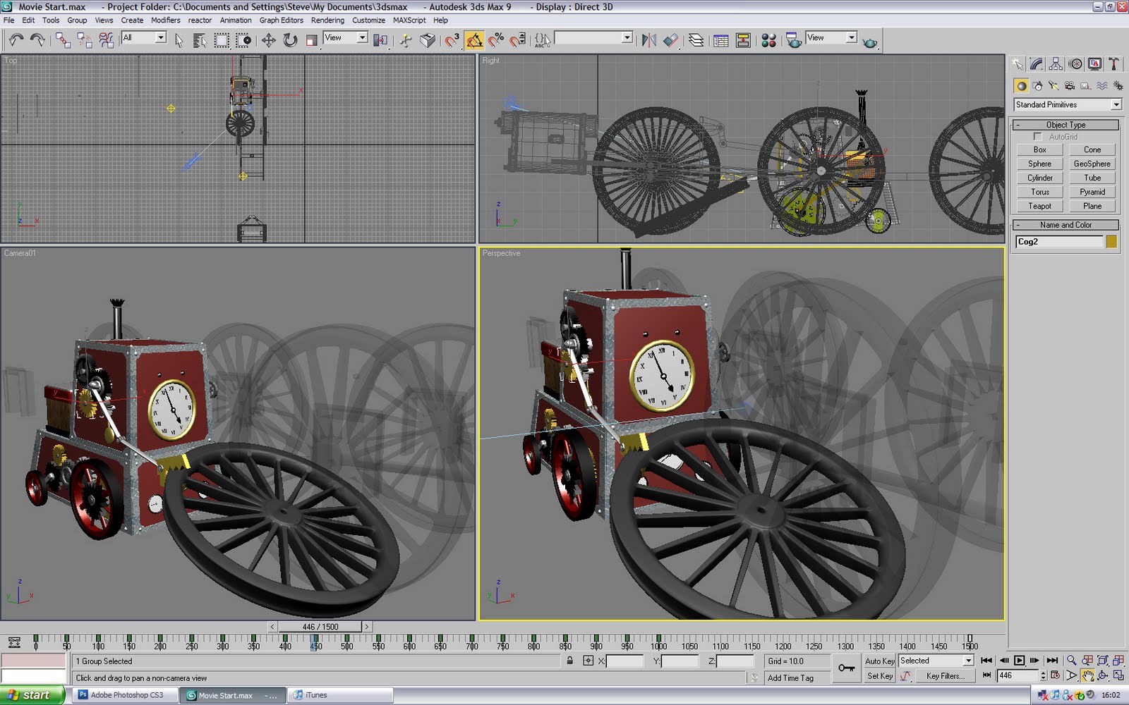 So how do you prop up a heavy wheel? It's too heavy to just flip on its side in a single movement. In fact it'd be probably be so heavy that you couldn't lift it cleanly. My guess, much like handling any other heavy object: Is that you get your hands beneath it, and start to lift it to the point where you can quickly lift it and put your weight beneath it. From here, you can lift the full weight with your entire body (Not just your arms / back). Thus, the same principle applied here! The first step was therefore to have SteamBot lifting the wheel before it could put its weight behind it. So we started with it gripping the edge and starting to lift, but as it does you, you will see that it wraps its claw around, so that it has a more secure grip.
 Next step is to put your weight behind it. Because it was too large and SteamBot is not able to crouch down, the best way of tackling this was to have SteamBot quickly 'throw' the wheel up, creating a sufficient gap to roll in and put its weight behind it. This bit was pretty easy, as I just had to fling SteamBot's arm up and move it forward. The trick bit was moving the wheel. The movement had to give off the impression that the wheel was exceptionally heavy (Rather than drifting in air and softly gliding back down), and so it had to move slightly, and immediately fly down with a lot of force.
 The final bit was the easiest. With its weight now behind the wheel, SteamBot only had to trundle forward and straighten its arm. Providing it was made slow enough, so that the wheel still looked like it carried a lot of weight, the animation was pretty simple.
 Of course, the wheels and the chassis weren't the only components of SteamBot. There were a ton of cogs on the right hand side, and the Steam-Pump on the left. There were also a ton of dials and gauges, not to mention the all-important arm! The arm in pariticular needed to have a personality (An odd thing to say). The fact that SteamBot's eyes and top-section were static meant that it was difficult to put across any emotion from them. The personality of SteamBot had to come directly from its movements and the arm. As a result, the arm would swing as if SteamBot was taking a casual stroll, and wave about opening and closing when in a state of panic. It's very subtle and, to be honest, probably not noticable, but it adds a strong sense of personality and character.
 Now, there was a lot to move! It was made easier by being built up in stages, where each new element would be incorporated into the entire film, before the next one was made. The 2 bare essentials were the arm and the chassis movement. Everything else is eye candy. So I started with the basic movement (Not even rocking) and letting the arm move and grab the essential things. From here, I added more rocking and lurching and arm flailing. After this, I was able to rotate the wheels to mirror the movements, and work in the cog and pendulum movements too.
So how did I make such a video? The tricks will be revealed over the next set of posts!

 And here it is! The finished model of SteamBot! All textured and ready to go! *sniff* They grow up so fast...

 The first step was to continue the clockwork theme of the right-hand side, and build in a few more gears and cogs (And even a pendulum)
 The unit was round ready to house an arm. I decided that the large black gear on the right would be the ideal for this.
 The 'shoulder' of the arm unit was made from a pair of cylinders (Pushed into the model so they look semi-circular), and linked to the cog (So that it moved as one). The upper arm and forearm were both simple cylinders (With a few smaller cylinders acting as the joints). As each part of the arm was built on, it was linked with the previous section, so that it could all move as one. Now, if the shoulder moves, the rest of the arm will move with it. If the upper arm moves, so does the fore-arm. And the forearm can move independently (But later moves the 'hand' when it moves)
 The hand clamp was constructed from a pair of splines (Drawn from the line tool), linked with a cylinder. As before, these were linked to the forearm (So that they move if the rest of the arm moves), and the pivots of both jaws were moved so that they rotated around the cylindrical join.
 With this in place, the arm was now finished!
 The job of creating the cogs/gears was made exceptionally easy with the lovely spline-drawing tool that was the 'Star'. Not only could you state how many points it had, but also the respective radii (How large the shape was, and how long the points were). With this, it wasn't hard to have a set of gears all created. All they required were a few bolts, and then it was a simple case of snapping them together.
 The final 'touch' to this section was to add a small drive shaft to the gear at the back, connecting to the rear wheel. Again, more eye candy. It's easy to get hooked on the stuff!
 The first step was the create the Steam Tank on its back. In essence, the power part of the engine. This was simply made from a lot of boxes stacked on top of eachother, with a quick, helpful blast of TurboSmooth for good measure.
 Next step was the all-important Steam chimney (What steam-powered locomotive would not have this stereotypical object?). Created from a cylinder, with a cone acting as the base. The top of the chimney (The spiky opening) was created from another cone (Only upside down). In 'Edit Poly' mode, every other vertex of the rim was pulled downward, creating the all-important serrated edge.
 The pipe on the side of the chassis was formerly a torus ring. However, in the 'Edit Poly' mode, it was creully pulled into the shape of a large pipe. The nuts were easy to make. (Little handy trick for anyone reading this) Take a cylinder, and in the object properties, switch 'Sides' down to 6, and switch off 'smooth'. There you go, one basic nut shape.
 A few more nuts were created, and a smaller version of the main wheels was also built onto them, to create a valve for the pipe. (Pure eye candy... but very tasty eye candy if I do say so myself)
 The pipe-work for the pump was all built using similar methods to those covered. All the pipes were former torus rings (Stretched out and with faces deleted) unless straight, in which case a cylinder sufficed. More nuts and connectors were added for greater authenticity (And to make it look even nicer)
 The pump was originally housed (and planned) on the side of the lower chassis. However, when the model was incorporated, the pump was too close to the chassis to realistically be able to push the wheel (It stuck out too far!). The drive shaft would end up going through the wheel, to realistically move it...
 As a result, the pump was moved a lot higher up, and at an angle to the wheel (The idea was inspired by 'The Rocket', seen below and snapped from the Museum of Power). At this point, the pump was in a stronger location, and the drive shaft was subsequently added to it
 The finishing touch was to create a pivot for the drive shaft (As it would have to rotate slightly as it travels around the wheel), and the result is what you see directly above! Now SteamBot is finally starting to look the part! Onto the next side...